A band-pass filter is a device that passes signals only within a certain frequency band, suppressing the low-frequency and high-frequency components. Its circuit design is usually implemented with LC circuits or operational amplifiers, depending on the required accuracy and applications.
This page is a utility for simulating band-pass filter online with specified initial values.
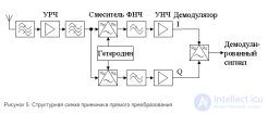
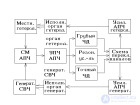
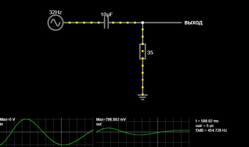
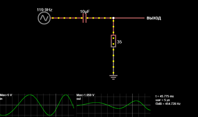
Structure: A band-pass filter can be thought of as a combination of a low-pass filter (LPF) and a high-pass filter (HPF) connected in series.
Parameters:
Lower cutoff frequency (f₁) — below it the signal is suppressed.
Upper cutoff frequency (f₂) — above it the signal is also suppressed.
Bandwidth (Δf = f₂ – f₁) — the range of frequencies that pass through the filter.
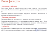
Types of implementation:
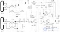
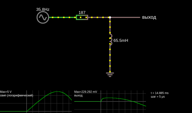
LC filters (inductors and capacitors) — used in radio engineering, providing a high quality factor.
RC filters based on operational amplifiers — convenient for low-frequency signals and integration into analog circuits.
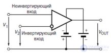
Active filters — use op-amps, do not require inductors, and allow the gain to be adjusted.
| Filter type | Elements | Advantages | Disadvantages | Application |
|---|---|---|---|---|
| LC band-pass | Inductors + capacitors | High quality factor, suitable for radio frequencies | Bulky inductors, difficult to tune | Radio receivers, transmitters |
| RC on op-amp | Resistors + capacitors + op-amp | Compactness, ease of implementation | Frequency limitation (up to hundreds of kHz) | Audio equipment, sensors |
| Active filter | Op-amp + RC | Ability to amplify, flexibility | Requires power supply, op-amp noise | Signal processing systems |
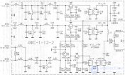
LC filter: a series inductor and capacitor form a resonant circuit tuned to the desired band.
Op-amp filter (for example, a biquad): a combination of RC circuits and an amplifier forms a passband with adjustable gain.
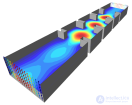
Multistage filters: several stages are connected to increase the steepness of the frequency-response roll-off.
Quality factor (Q): determines the selectivity of the filter. The higher the Q, the narrower the passband.
Matching: it is important to take into account the input and output impedance to minimize losses.
Implementation: active filters are more convenient for low frequencies, while LC circuits are used for radio frequencies.


Comments