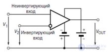
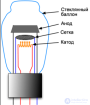
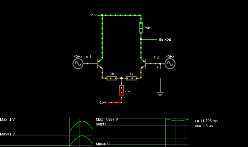
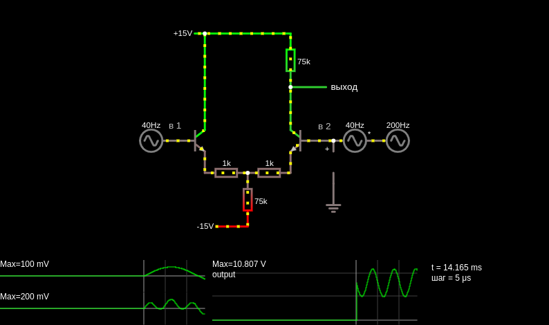
This is a differential amplifier built with two transistors and a current source. The output equals the voltage difference between the two inputs. Input 1 is a 40 Hz signal, and input 2 is a 40 Hz signal with small voltage spikes added. (In this simulation the two signals are added simply by connecting two sources in series, which is convenient but unrealistic.) The output is just the voltage spikes. The common-mode rejection ratio of this circuit is much better than in the previous example; the 40 Hz sine wave is not visible at the output at all. The two inputs are connected to the bases of the two transistors. The two emitters are tied together. In the differential-mode case, when input 1 increases and input 2 falls by the same amount, the base current through transistor 1 increases and through transistor 2 decreases. A corresponding increase in collector current also occurs. The total current through the current source does not change. The decrease in current through the right transistor causes the output to rise. When input 1 falls and input 2 rises, the output falls. In the common-mode case, when input 1 and input 2 rise together, the current source resists any change in the base currents. The emitter voltage rises in accordance with the changes at the input. Since the collector current of transistor 2 has not changed, the output signal has not changed either.
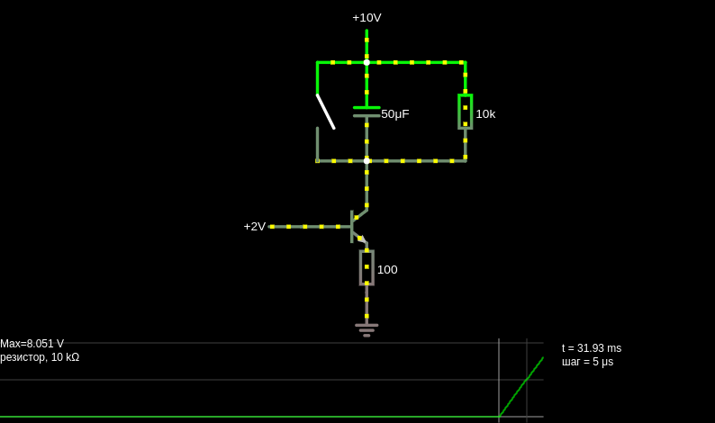
This page is a utility for simulating differential amplifier (common-mode, current source) online with specified initial values.

Comments