Lecture
A business process is a set of interrelated activities or tasks aimed at creating a specific product or service for consumers. As a graphic description of the activities used flowcharts of business processes.
There are three types of business processes:
The business process starts with consumer demand and ends with satisfaction. Process-oriented organizations are trying to eliminate barriers and delays arising at the junction of two different divisions of the organization when performing the same business process.
A business process can be decomposed into several subprocesses, procedures, and functions that have their own attributes, but are also aimed at achieving the goal of the underlying business process. Such an analysis of business processes usually includes the mapping of a business process and its sub-processes, separated between certain levels of activity.
Business processes should be structured in such a way as to create value and value for consumers and exclude any optional or unnecessary activity. At the exit of properly constructed business processes, the value for the consumer and profitability (lower cost of production of goods or services) increase.
Business processes can be analyzed differently depending on the purpose of the simulation. Business process analysis can be used in business modeling, value analysis, organizational structure formation, business process reengineering, and technological process automation.
One of the methods for analyzing current activities is to create a business process model “as is” (eng. As is ). After that, the business process model is subjected to critical analysis or processed by special software. According to the results of the analysis, a business process model “as it should be” (eng. To be ) and an action plan to introduce the necessary changes are formed.
There are many notations used to model business processes, for example:
Business process reengineering (eng. Business process reengineering ) - a fundamental rethinking and radical redesign of business processes to achieve the maximum effect of production, economic and financial and economic activities, drawn up by the relevant organizational, regulatory and regulatory documents. Reengineering uses specific means of presenting and processing problem information that is understandable to both managers and developers of information systems.
The meaning of business process reengineering in two of its main stages:
Business process modeling is the process of reflecting a subjective vision of the workflow in the form of a formal model consisting of interrelated operations.
The purpose of modeling is the systematization of knowledge about the company and its business processes in a visual graphical form more convenient for analytical processing of the information received.
Currently, the computer technology market is represented by a number of special programs that allow inspecting an enterprise and building a model. The choice of methodology and tools with which business processes are modeled is not of fundamental importance. There are standardized, time-tested methodologies and tools with which you can examine the enterprise and build its model. Their key advantage is simplicity and accessibility to mastering.
Many modern methodologies for modeling business processes are based on the SADT (Structured Analysis and Design Technique) methodology, the IDEF (Icam DEFinition, where Icam is Integrated Computer-Aided Manufacturing) standards and algorithmic languages. The main types of methodologies for modeling and analysis of business processes:
Business Process Modeling. The most widely used business process description methodology is the IDEF0 standard. The models in IDEF0 notation are intended for a high-level description of the company's business in a functional aspect.
Description of the work flow (Work Flow Modeling). The IDEF3 standard is intended to describe workflows and is close to algorithmic methods for constructing flowcharts.
Description of data flows (Data Flow Modeling). Notation DFD (Data Flow Diagramming), allows you to reflect the sequence of work performed during the process, and the flow of information circulating between these works.
Other methodologies.
The main advantage of the idea of analyzing the business processes of an enterprise through the creation of its model is its universality. First, the modeling of business processes is the answer to almost all questions relating to the improvement of the enterprise and its competitiveness. Secondly, the head or the management of the enterprise, who have implemented a specific methodology, will have information that will allow them to independently improve their enterprise and predict its future.
The essence and importance of business process modeling
Modeling business processes allows you to analyze not only how the company works as a whole, how it interacts with external organizations, customers and suppliers, but also how the activity is organized in each individual workplace.
There are several approaches to the definition of the concept of "modeling business processes":
business process modeling is a description of a company's business processes, which allows a manager to know how ordinary employees work, and ordinary employees how their colleagues work and what end result their entire activity is directed to;
Business process modeling is an effective means of finding ways to optimize a company’s operations, allowing you to determine how a company works as a whole and how activities are organized at each workplace .;
business process modeling is a means of predicting and minimizing the risks arising at various stages of the reorganization of an enterprise;
business process modeling is a method to evaluate the current activities of an enterprise in relation to the requirements for its operation, management, efficiency, final results of operations and the degree of customer satisfaction;
Business process modeling is a method that allows valuing each process, taken separately, and all business processes in an enterprise, taken together;
Business process modeling is always the right way to identify current problems in an enterprise and anticipate future ones.
Modern enterprises are constantly forced to improve their operations. This requires the development of new technologies and business practices, improving the quality of the final results of activities and, of course, the introduction of new, more effective methods of management and organization of enterprises.
A business process is a logical, consistent, interrelated set of activities that consume resources, create value, and produce results. In the international standard ISO 9000: 2000, the term "process" is adopted, but at present these terms can be considered synonymous. Among the main reasons that motivate an organization to optimize business processes include the need to reduce costs or the duration of the production cycle, requirements imposed by consumers and the state, the introduction of quality management programs, mergers of companies, internal contradictions, etc.
Business process modeling is an effective means of finding ways to optimize a company’s operations, a means of predicting and minimizing risks arising at various stages of an enterprise’s reorganization. This method allows you to give a valuation of each individual process and all business processes of the organization in the aggregate.
Decisions on modeling business processes are usually made for the reasons presented in Figure 1.
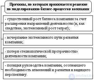
Figure 1 - Reasons for deciding on the modeling of business processes
Business process modeling involves many aspects of a company:
change in organizational structure;
optimization of functions of departments and employees;
the redistribution of rights and duties of managers;
change of internal regulatory documents and technology of operations;
new requirements for the automation of running processes, etc.
The purpose of modeling is the systematization of knowledge about the company and its business processes in a visual graphical form more convenient for analytical processing of the information received. The model should reflect the structure of the organization’s business processes, the details of their implementation and the sequence of workflow.
The modeling of an organization’s business processes includes two stages, structural and detailed.
Structural modeling of an organization's business processes can be performed in IDEF0 notation using BPwin tools or in UML using Rational Rose tools. Detailed modeling is performed in UML.
At the stage of structural modeling in the model should be reflected:
existing organizational structure;
documents and other entities used in the execution of simulated business processes and necessary for the simulation of document flow, with descriptions of their main meaning;
structure of business processes, reflecting their hierarchy from more general groups to private business processes;
interaction diagrams for final business processes, reflecting the sequence of creation and movement of documents (data, materials, resources, etc.) between actors.
The prepared model should be coordinated by architects and leading programmers, confirming that the structure of business processes is understandable.
Detailed modeling of business processes is performed in the same model and should reflect the required detail and should provide an unambiguous view of the organization’s activities.
The detailed business process model should include:
a set of precedents reflecting possible options for executing business processes "as is";
action diagrams that describe in detail the sequence of business processes;
interaction diagrams reflecting workflow patterns.
Models must be coordinated with leading experts of the organization with the necessary knowledge.
If, after building the models, no agreement has been reached, the necessary clarifications and corrections should be made to the model. The process of iteration (coordination, introduction of corrections and refinements) must be repeated until the moment of complete confirmation that the model is clear and unambiguously represents the details of business processes.
The basis of many modern methodologies for modeling business processes is the SADT (Structured Analysis and Design Technique) methodology and algorithmic languages used for software development.
The history of the development of business process modeling methodologies is summarized in the table below. For clarity, the history of the development of approaches to quality management is given in parallel.
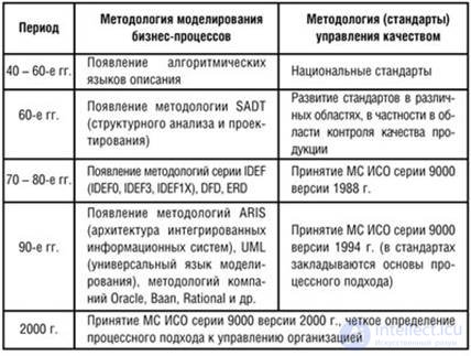
Figure 2 - The history of the development of business process modeling methodologies
Despite its distinction, mainly associated with the name of the diagrams and the types of objects used, modern methodologies for describing business processes are almost identical and are minor changes to classical standards.
Classical standards for describing a business process include the following:
DFD (Data Flow Diagram) is a standard for describing top-level processes and data streams that are transformed by the functions of this process.
The data flow diagram shows the work that is part of the business process, as well as the inputs and outputs of each work. These inputs and outputs represent either informational or material flows. In this case, the outputs of one work can be inputs for others.
WFD (Workflow Diagram) is a standard for describing workflows. Used to detail the business process functions.
The WFD notation has additional elements to describe a business process:
In the classical approach, WFD in this scheme does not show documents and arrows between business process operations indicate not flows of objects (informational and material), but flows or temporal sequence of work.
ERD (Entity Relaish Diagram) is a standard for describing an information model.
The ER model is one of the simplest visual data models (graphic notations). It allows you to designate the structure of "large strokes," in general terms. With its help, you can select key entities that are present in the model, and identify relationships that can be established between these entities. This general structure description is called the ER diagram.
Basic notations: ERD (Chen Notation), UML (Class Diargamm), IDEF1x.
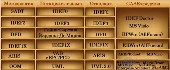
Classical standards DFD and WFD contain a set of symbols or symbols with which the business process is described. These designations are called the language or methodology for describing processes. In this case, this language or methodology is classic.
Nowadays, many other languages or methodologies describing business processes containing a slightly different notation have appeared in the world. Moreover, each methodology contains its own language and has its own name. Currently, this leads to some confusion among the end users who use these technologies in practice in their organization. Hence the seeming complexity of the application of process technologies.
In fact, despite its difference, mainly associated with the name of the diagrams and types of objects used, modern methodologies for describing business processes are almost identical and are minor modifications of the two classical schemes - DFD and WFD - Work Flow Diagram, which were considered.
Let's consider other modern languages of the description of business processes:
IDEF0;
DFD in the notation of Heine-Sarson and Jordan-de Marco;
IDEF3;
Oracle;
BAAN;
ARIS.
Swimmer lanes;
IDEF family of methodologies (Icam DEFinition, where Icam is Integrated Computer-Aided Manufacturing).
The most famous and widely used methodologies of this family:
The first common methodology to be considered is IDEF0.This language was invented by the US military in order to successfully replicate the business processes of aerospace enterprises. At one time, the US military faced the following problem. When designing the factories, it was noticed that each time it is necessary to perform the same step anew - to design the same control subsystems, which took additional time and resources. After that, it was proposed to develop a language or a drawing with which it would be possible to describe typical control subsystems and use the established schemes to build a new plant. The language that was invented and used for these purposes formed the basis of the methodology for describing business processes IDEF0.
Методология IDEF0 незначительно отличается от классической схемы описания бизнес-процессов DFD, которая была рассмотрена ранее. Основным отличием является наличие в языке дополнительной аналитики. Данный стандарт описания бизнес-процессов предлагает показывать не просто входы и выходы, как это делается в DFD – формате, он предлагает ввести три типа входов. Первый тип входов назвали так же входом, а два других входа назвали управлением и механизмами.
В стандарте IDEF0 c помощью входа показывают объекты – информационные и материальные потоки, которые преобразуются в бизнес-процессе. С помощью управления показывают объекты – материальные и информационные потоки, которые не преобразуются в процессе, но нужны для его выполнения. С помощью механизмов стали показывать механизмы, при помощи которых бизнес-процесс реализуется: технические средства, люди, информационные системы и т.д. Выход бизнес-процесса, описанного в стандарте IDEF0 полностью соответствует по смыслу выходу процесса, описанному при помощи DFD-схемы.
Четыре типа объектов, применяемых для описания входов и выходов в стандарте IDEF0, в английском варианте образуют сокращение ICOM и на схеме IDEF0 размещаются в строго отведенных местах относительно работ, которые называются функциональными блоками (Таблица 1).
Таблица 1. Название и размещение входов и выходов в стандарте IDEF0 относительно функционального блока.
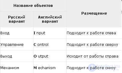
Давайте рассмотрим пример бизнес-процесса "Выточить деталь", который выполняет токарь. Входом процесса является заготовка из которой вытачивается деталь – она физически преобразуется в процессе. Для того, что бы токарь начал точить деталь ему нужно дать задание или план. Также ему понадобится чертеж с размерами детали. Так вот, чертеж, задание или план нужны для реализации бизнес-процесса и процесс без них не начнется, но по ходу выполнения процесса они не преобразуются. Согласно стандарту IDEF0 их относят к управлению. Для того, что бы выточить деталь нужен токарь, нужен станок – их относят к механизмам. Выходами или результатами бизнес-процесса является деталь (рис. 3).
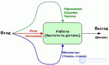
Fig.3. Стандарт описания бизнес-процесса IDEF0.
Стандарт IDEF0 получил большое распространение в США и активно используется в России. Ввиду того, что в стандарте IDEF0 появилась дополнительная аналитика по сравнению с классическим стандартом DFD, схемы бизнес-процессов получаемые при описании в стандарте IDEF0 выглядят более сложными с точки зрения менеджеров компании, в виду ограниченного наличия у них свободного времени. Данная сложность часто приводит к тому, что менеджеры, особенно высшего уровня, которые должны принимать активное участие в проекте по описанию и оптимизации деятельности компании, "отказываются" от работы с IDEF0. В данном случае IDEF0 - является излишне информационно насыщенным и сложным стандартом.
Второй недостаток стандарта IDEF0 связан с тем, что он дает больше поводов и возможностей сторонникам сопротивлений изменениям притормозить проект по описанию и оптимизации бизнес-процессов и дискредитировать его идею. Это также связано с усложненной аналитикой стандарта IDEF0, которая часто дает повод задуматься и задавать следующие вопросы: "А правильно ли, что этот объект отнесен ко входу? Может его отнести к управлению?"
Тем не менее, стандарт IDEF0 имеет большое распространение в России, так как по нему существует много книг и различных информационно-методических материалов. Также существуют программные продукты, поддерживающие данный стандарт, овладеть которым несложно.
Практика показала, что стандарт IDEF0 целесообразно использовать в проектах по описанию и оптимизации локальных бизнес-процессов, в небольших проектах в которых больше участвуют и принимают решения специалисты предметных областей, а руководители высшего уровня привлекаются для принятия решений по минимуму. In fig. 4 приведена диаграмма IDEF0 верхнего уровня бизнес-процесса "Увольнение сотрудника".
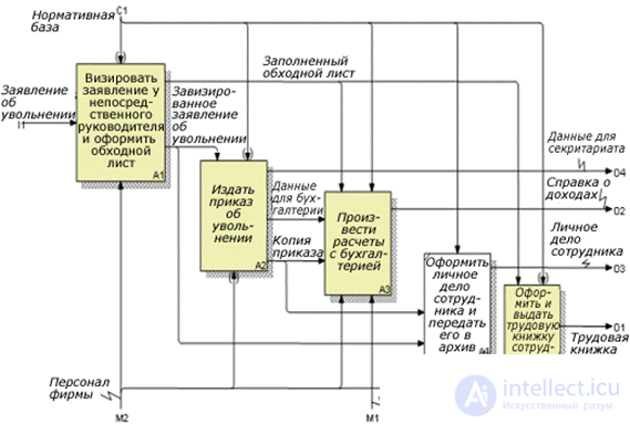
Fig. 4. Диаграмма IDEF0 верхнего уровня бизнес-процесса "Увольнение сотрудника".
Следующий стандарт описания бизнес-процессов, который получил распространение, был разработан на основе развития классической методологии DFD. Данный стандарт представлен двумя немного различающихся вариантами, которые называют нотациями. Первая из них называется нотацией Гейна Сарсона, вторая нотацией Йордона-Де Марко.
Гейн Сарсон, предложил классическую DFD-схему немного усложнить. Он предложил ввести дополнительный объект, с помощью которого показываются места бизнес-процесса, в которых хранится информация, либо материальные ресурсы. Примерами таким мест являются архив, в котором хранятся документы, база данных, в которой хранится информация, либо склад, на котором хранятся материальные ресурсы. Данный объект получил название - хранилище данных. На DFD-схемах в нотациях Гейна-Сарсона и Йордона-Де Марко также используются объекты, с помощью которых показывают внешних субъектов, с которыми бизнес-процесс взаимодействует. Данные объекты называют внешними сущностями. In fig. 5 приведен пример DFD-схемы бизнес-процесса "Оформлении и выдача трудовой книжки сотруднику при увольнении", разработанной в нотации Гейна-Сарсона.
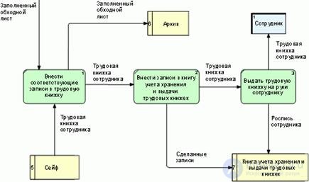
Fig. 5. DFD-схема бизнес-процесса "Оформлении и выдача трудовой книжки сотруднику при увольнении" в нотации Гейна-Сарсона.
На данной схеме в качестве хранилища данных выступают сейф, в котором хранятся трудовые книжки и архив, в который помещается заполненный обходной лист. В качестве внешней сущности выступает сотрудник, который увольняется и который получает выход рассматриваемого бизнес-процесса – трудовую книжку.
Вторая нотация Йордона-Де Марко методологии DFD была названа в честь разработавшего ее специалиста Йордона-Де Марко. В первом приближении эта нотация аналогична нотации Гейна Саросна, за исключение форм объектов: для описаний операций бизнес-процесса вместо закругленных прямоугольников стали использоваться круги, немного видоизменились и другие объекты – хранилище данных и внешние сущности (рис. 6).
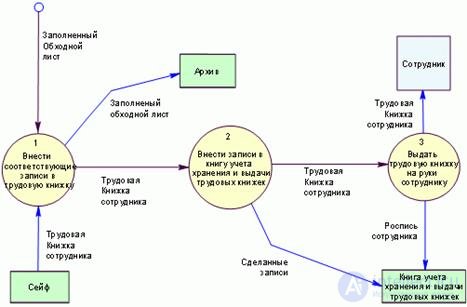
Fig. 6. DFD-схема бизнес-процесса "Оформлении и выдача трудовой книжки сотруднику при увольнении" в нотации Йордона-Де Марко.
В таблице 2 приведены названия, обозначения и смыл элементов, используемых при построении DFD-схемы бизнес-процесса в нотациях Гейна-Сарсано и Йордона-Де Марко.
Таблица 2. Элементы методологии DFD в нотацияхГейна-Сарсано и Йордона-Де Марко.
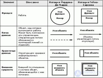
Стандарт IDEF0, который был рассмотрен ранее является развитием классического DFD – подхода и предназначен для описания бизнес-процессов верхнего уровня. Для описания временной последовательности и алгоритмов выполнения работ стандарт IDEF0 не подходит. Для решения этой задачи стандарт IDEF0 получил дальнейшее развитие в результате чего был разработан стандарт IDEF3, который входит в семейство стандартов IDEF.
Стандарт IDEF3 предназначен для описания бизнес-процессов нижнего уровня и содержит объекты – логические операторы, с помощью которых показывают альтернативы и места принятия решений и в бизнес-процессе, а также объекты – стрелки с помощью которых показывают временную последовательность работ в бизнес-процессе (рис. 7).

Fig. 7. Схема бизнес-процесса в стандарте IDEF3.
В отличие от классической методологии WFD в стандарте IDEF3 связи между работами делятся на три типа, обозначения, названия и смыл которых, приведены в таблице 3.
Таблица 3. Типы связей между работами в стандарте IDEF3.
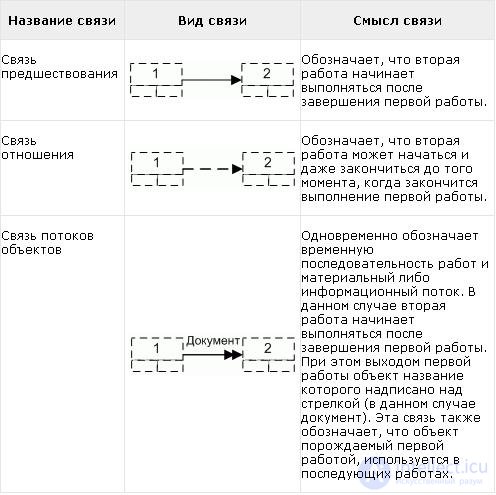
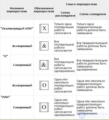
Помимо наличия нескольких типов связей между работами в стандарте IDEF3 логические операторы, которые в данном случае называются перекрестками также делятся на несколько типов: "Исключающий ИЛИ", "И" и "ИЛИ".
Перекресток "Исключающий ИЛИ" обозначает, что после завершения работы "A" (рис. 8), начинает выполняться только одна из трех расположенных параллельно работ B, С или D в зависимости от условий 1, 2 и 3. Перекресток "И" обозначает, что после завершения работы "A", начинают выполняться одновременно три параллельно расположенные работы B, С и D. Перекресток "ИЛИ" обозначает, что после завершения работы "A", может запуститься любая комбинация трех параллельно расположенных работ B, С и D. Например может запуститься только одна из них, могут запуститься три работы, а также могут запуститься двойные комбинации В и С, либо C и D, либо B и D. Перекресток "Исключающий ИЛИ" является самым неопределенным, так как предполагает несколько возможных сценариев реализации бизнес-процесса и применяется для описания слабо формализованных ситуаций.
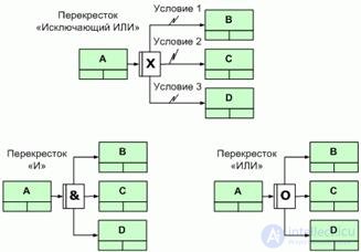
Fig. 8. Применение перекрестков "Исключающий ИЛИ", "И" и "ИЛИ" - схемы расхождения.
Перекрестки "И" и "ИЛИ" подразделяются еще на два подтипа – синхронные и асинхронные. Перекрестки синхронного типа обозначают, что работы В, С и D запускаются одновременно после завершения работы A. Перекрестки асинхронного типа требований к одновременности не предъявляют.
Приведенные на рис. 5 схемы взаимосвязи работ и перекрестков называются схемами расхождения, так как от перекрестков расходятся несколько работ. Существует и другие схемы взаимосвязи перекрестков и работ – это так называемые схемы схождения, когда к перекрестку подходит несколько работ (рис. 9).
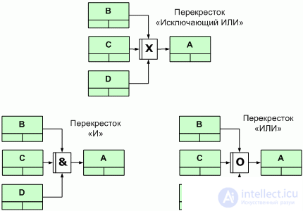
Fig. 9. Применение перекрестков "Исключающий ИЛИ", "И" и "ИЛИ" - схемы схождения.
В таблице 4 приведены обозначения, названия и смысл всех типов перекрестков как в схемах схождения, так и в схемах расхождения.
Таблица 4. Обозначения, названия и смысл типов перекрестков в схемах схождения и расхождения.
Последним отличием стандарта IDEF3 в отличие от классической методологии WFD является использование на схеме бизнес-процесса такого элемента как "объект ссылки", который связывается с работами и перекрестками. С помощью объектов ссылки показывается прочая важная информация, которую целесообразно зафиксировать при описании бизнес-процесса.
Следующие подходы описания бизнес-процессов были разработаны компаниями, занимающиеся разработкой и внедрением интегрированных информационных систем. Сделано это было по следующей причине. Оказывается, для того, чтобы эффективно провести автоматизацию и правильно настроить информационную систему на деятельность компании, необходимо вначале описать ее бизнес-процессы, описать организационную структуру и только потом приступить к внедрению информационной системы.
Три наиболее крупных разработчика информационных систем: SAP/R3, BAAN и ORACLE для повышения эффективности внедрения своих информационных систем разработали свои стандарты и программные продукты, с помощью которых описывается бизнес-деятельность компании. Каждый из этих стандартов содержит несколько бизнес-моделей, с помощью которых описываются бизнес-процессы, организационная структура, а также строятся прочие бизнес-модели.
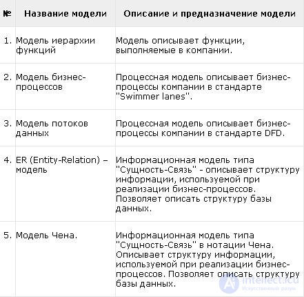
Давайте рассмотрим стандарт, который использует компания ORACLE. Методология ORACLE содержит 5 бизнес-моделей, название, описание и предназначение которых приведено в таблице 5.
Таблица 5. Модели методологии ORACLE.
При описании бизнес-процессов с использованием методологии ORACLE наиболее часто применяется вторая согласно перечню таблицы 5 модель бизнес-процессов. Построение этой модели основано на подходе "Swimmer lanes", который представляет из себя смесь классических DFD и WFD стандартов и имеет одну отличительную особенность. Диаграмма, на котором рисуется схема бизнес-процесса разделена по горизонтали на дорожки. Каждая дорожка принадлежит определенному структурному подразделению или должности, участвующей в бизнес-процессе. Те операции бизнес-процесса, которые выполняются этим структурным подразделением, размещаются в зоне соответствующей дорожки. Такой подход позволяет наглядно показать распределение ответственности в бизнес-процессе и продемонстрировать степень его организационной фрагментарности (рис. 10).
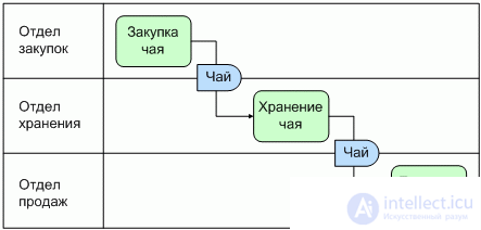
Fig. 10. Пример описания бизнес-процесса "Торговля чаем" для функциональной организационной структуры компании "Эврика".
Одним из недостатков формата "Swimmer lanes" является то, что в данном случае более трудно отследить временную последовательность работ, а так же критический путь бизнес-процесса, что актуально при проведении временной оптимизации.
IDEF1X - методология описания данных. Применяется для построения баз данных.
IDEF1X является методом для разработки реляционных баз данных и использует условный синтаксис, специально разработанный для удобного построения концептуальной схемы. Концептуальной схемой мы называем универсальное представление структуры данных в рамках коммерческого предприятия, независимое от конечной реализации базы данных и аппаратной платформы. Будучи статическим методом разработки, IDEF1X изначально не предназначен для динамического анализа по принципу "AS IS", тем не менее, он иногда применяется в этом качестве, как альтернатива методу IDEF1. Использование метода IDEF1X наиболее целесообразно для построения логической структуры базы данных после того, как все информационные ресурсы исследованы (скажем с помощью метода IDEF1) и решение о внедрении реляционной базы данных, как части корпоративной информационной системы, было принято. Однако не стоит забывать, что средства моделирования IDEF1X специально разработаны для построения реляционных информационных систем, и если существует необходимость проектирования другой системы, скажем объектно-ориентированной, то лучше избрать другие методы моделирования.
There are several obvious reasons why IDEF1X should not be used in the case of building non-relational systems. First, IDEF1X requires the designer to identify key attributes in order to distinguish one entity from another, while object-oriented systems do not require the specification of key keys in order to identify objects. Secondly, in cases where more than one attribute uniquely identifies the entity, the designer must define one of these attributes as the primary key and all the others as secondary. And thus, the IDEF1X model built by the designer and transferred to the programmer for the final implementation is incorrect for applying the methods of an object-oriented implementation, and is intended for building a relational system
1.7.1 Entity Relationships
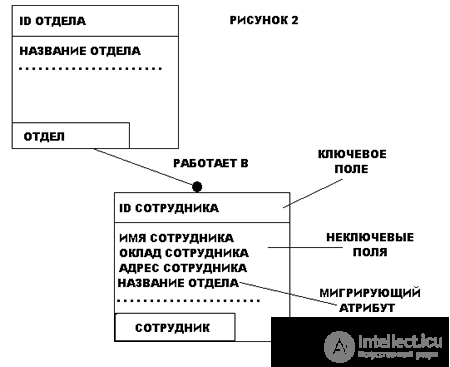
Links in IDEF1X are links, connections, and associations between entities. Below, in the figure, are a number of examples of relationships between entities:
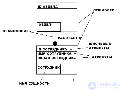
The entity is described in the IDEF1X diagram by a graphical object in the form of a rectangle. Figure 2 shows an example of an IDEF1X chart.
1.7.2 Benefits of IDEF1X
The main advantage of IDEF1X, as compared to other numerous methods of developing relational databases, such as ER and ENALIM, is the strict and strict standardization of modeling. The established standards allow us to avoid different interpretations of the constructed model, which is undoubtedly a significant disadvantage of ER.
IDEF4 is an object-oriented methodology. Reflects the interaction of objects. Convenient for creating software products in object-oriented languages (for example, C ++). So far, in my opinion, I have not found wide distribution. UML is more commonly used now.
SADT - Structured Analysis and Design Technique Methodology. Based on the concepts of functional modeling. It is a methodology that reflects such system characteristics as control, feedback and performers. It originated in the late 60s.
A system description using SADT is called a model. SADT models use both natural and graphic languages. To transfer information about a particular system, the source of a natural language is the people who describe the system, and the source of the graphic language is the SADT methodology itself. The graphic language SADT provides the structure and exact semantics of the model's natural language. The graphic language SADT organizes natural language in a completely definite and unambiguous way, due to which SADT allows describing systems that until recently did not respond to an adequate representation.
From the point of view of SADT, the model can be focused either on the functions of the system or on its objects. Function-oriented SADT models are usually called functional models, and object-oriented systems are data models; the functional model represents, with a required degree of detail, a system of functions, which in turn reflect their relationships through system objects. Data models are dual to functional models and are a detailed description of system objects related by system functions. The full SADT methodology supports the creation of multiple models for more accurate description of a complex system.
The methodology is used for detailing business processes and is a modification of the WFD and DFD standards. Chart with business process, divided into tracks. Each track corresponds to a structural unit, or a position involved in the business process. And those operations that are performed by the structural unit are located in the area of its track.
The methodology is based on the Rumler-Breich diagram. Rumler proposed to divide the chart into tracks according to the following principle:
The well-known BPMN business process modeling notation is a direct descendant of the Rumler-Breich diagram.
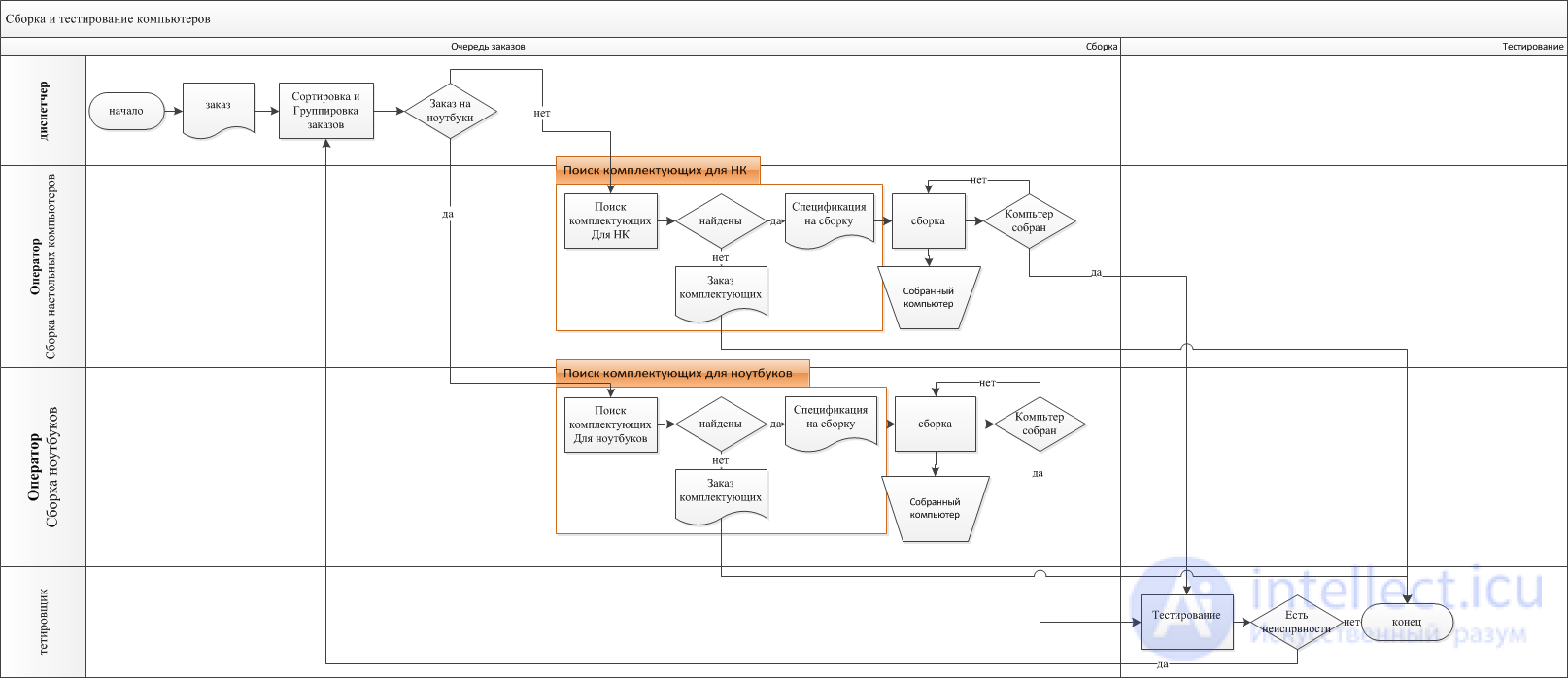
example of swimmer lanes diagrams in rumler-breich notation
ARIS Methodology
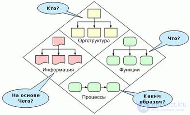
According to the methodology, the organization is considered from four points of view:
Among the many types of diagrams that are offered in the methodology, the following can be singled out:
The same methodology supports BPMN notation.
One of the modern methodologies of business modeling, which has become widespread in Russia, is the ARIS methodology, which stands for Architecture of Integrated Information Systems - the design of integrated information systems. It is used by the ARIS Toolset tool.
The ARIS methodology is currently the most voluminous and contains about 100 different business models used to describe, analyze and optimize various aspects of the organization’s activities. Some models of the ARIS methodology are used in the configuration module of the integrated information system SAP / R3, which is used when introducing the system and setting it up for the company's activities. Due to the large number of business models, the ARIS methodology divides them into four groups (Fig. 11):
Group "Organizational Structure".
It consists of models with the help of which the organizational structure of the company is described, as well as other elements of the internal infrastructure of the organization.
Group "Functions".
Consists of models used to describe the strategic goals of the company, functions and other elements of the functional activities of the organization.
Group. "Information".
It consists of models with the help of which information is described, which is used in the activities of the organization.
Group "Processes".
Consists of models used to describe business processes, as well as various relationships between structure, functions, and information.
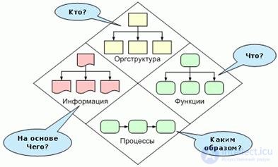
Fig. 11. Model groups of ARIS methodology.
The big advantage of the ARIS methodology is ergonomics and a high degree of visualization of business models, which makes this methodology convenient and accessible for use by all employees of the company, ranging from top managers to ordinary employees. In the ARIS methodology, color is meaningful, which increases the susceptibility and readability of business model diagrams.
For example, structural units by default are displayed in yellow, business processes and operations in green. In addition to a larger number of models compared to other methodologies, the ARIS methodology has the largest number of different objects used in building business models, which increases their analyticity.
For example, material and information flows in process flow diagrams are denoted by objects of different shape and color, which allows you to quickly determine the type of flow.
Despite the greater number of models in the ARIS methodology in projects for the description and optimization of activities, in general, no more than ten of them are used. Methodology ARIS positions itself as a constructor, from which a local methodology is developed for a specific project, depending on its goals and objectives, consisting of a small number of required business models and objects.
In the general case, practice has shown that the projects most frequently used are the models shown in Table 6.
Table 6. The most commonly used in practice model methodology ARIS.
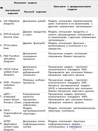
The "Chart of Goals" model - OD is used to describe the company's strategic goals, their hierarchical order, as well as the relationship of the goals with the products and services produced by the company and the business processes that support their production (Fig. 12)
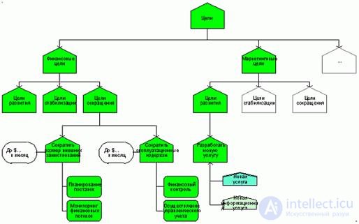
Fig. 12. Model "Chart goals" - OD / ARIS.
The Product and Services Tree Model - PST is used to describe products and services produced in a company, as well as links to the company's strategic goals, business processes that support their production (Fig. 13).
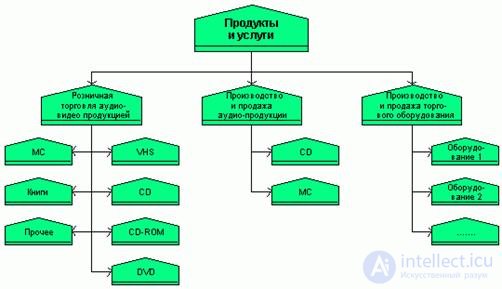
Fig. 13. Model "Tree of products and services - PST / ARIS".
The Function Tree model - FT describes the functions performed in a company and their hierarchy. This model is often used to build a tree of business processes of the company (Fig. 14).
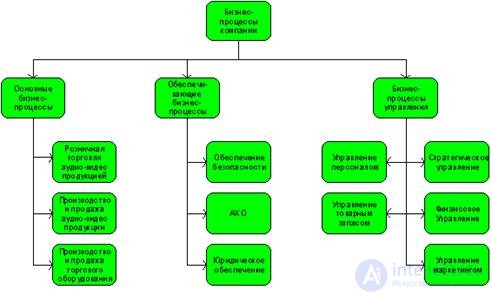
Fig. 14. Model "Function Tree" - PST / ARIS.
The "Process Environment Chart" model - FAT allows you to describe the environment or the boundaries of a business process, showing its inputs, outputs, suppliers and customers (Fig. 15).

Fig. 15. Process Environment Chart model - PST / ARIS.
The "Value Chain Chart" model - VACD is a prototype of the classic DFD standard and is used to describe top-level business processes. An additional difference of this and other process models is that the information and material flows on the VACD scheme are depicted not as arrows, but as objects. In addition, for each type of stream uses its own object. On the VACD model, the ARIS methodology, in contrast to the classical approach, also uses logical connections between works, which allow displaying the logical sequence of work execution. One of the variants of a logical sequence can be a temporary sequence of work execution, which is typical of the classical WFD approach. (Fig. 16). 
Fig. 16. Advanced Event-Driven Process Chain - eEPC / ARIS.
The Process Selection Matrix model - PSM is the prototype of the classic DFD standard and is used as an alternative for the VACD model. The process selection matrix in relation to the value chain diagram is, on the one hand, a simpler variant of the process description, on the other hand this model contains additional objects that allow to show other aspects of the business process. The simplicity of the business process selection matrix is related to the fact that information and material flows are not shown on this model. As for the other aspects, this model allows one to show compactly and visually the various options for performing the business process that is being described. Accordingly, the process selection matrix should be used instead of the value chain diagram in cases when the described business process has several variants, each of which lays down the basic scheme. An example of applying the process selection matrix to describing the activities of the Evrika company, which has a functional organizational structure, is shown in Fig. 17
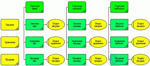
Fig. 17. Model "Process Selection Matrix" - PSM / ARIS.
The "Extended event driven Process Chain" model - eEPC is a prototype of the classic WFD standard and is used to describe lower-level business processes. An additional difference between the eEPC model and the classical WFD scheme is the presence of an object on the model, which is called an event. With the help of events, a fact, time or event is triggered that initiates the beginning of the process, as well as the fact or time of their completion (Fig. 18).
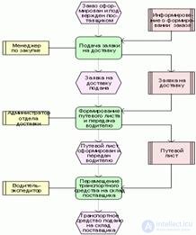
Fig. 18. Model "Extended chain of event-driven processes" - VACD / ARIS.
The model "Organizational structure" - ORG is used to describe the organizational structure of the company. This model depicts structural units, groups, positions, roles, and other elements of the organizational structure and the relationship between them (Fig. 19).
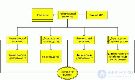
Fig. 19. Model "Organizational Structure" - ORG / ARIS.
Information Systems Type Chart Model - ASTD is used to describe the structure of information systems used in a company. This model shows the types and modules of information systems, software products, the relationship between them and the organization's business processes that they automate (Fig. 20).
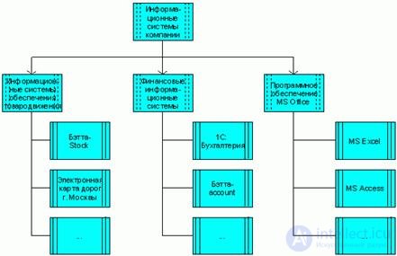
Fig. 20. Information Systems Type Chart Model - VACD / ASTD.
For storing models in ARIS, an object database is used, and a new database is created for each project. There are various database administration functions, such as access control. The database is a hierarchical repository of models.
The work on creating a model should be governed by strict and voluminous modeling agreements (standards), ARIS supports a mechanism of methodological filters that allow the user to use only a specific set of schemes and objects. The development of such agreements requires considerable time and highly qualified specialists. If a project using ARIS begins without a detailed study of such agreements, then the probability of creating models of business processes that do not answer the questions posed is very high.
1.12 Methodology used by consulting companies
Most consulting companies in projects to optimize the activities of organizations generally use a typical methodology for describing business processes. This methodology consists of two types of business models, one of which is used to describe the business processes of the upper level and is the prototype of the classical DFD model, and the second is used to describe the processes of the lower level and corresponds to the principles of building the classical WFD scheme.
The top-level model and the principles of its construction are presented in fig. 21.
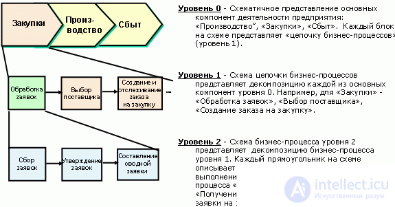
Fig. 21. A model for describing top-level business processes used by consulting companies.
The model of lower-level business processes using the Swimmer lanes approach is presented in Fig. 22
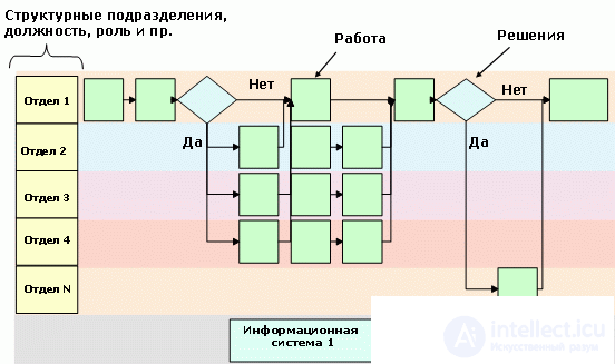
Fig. 22. The model of the description of business processes of the lower level, used by consulting companies.
1.13 Methodology Betec (©)
Based on the use of various modern methodologies for describing business processes in Russian companies, the consulting company "Business - Engineering Technologies" developed a methodology for describing activities, a company that embodied the best elements of the above methodologies. This methodology, called Betec (©), consists of models by which they describe the company's business activities and are conventionally grouped into the following sections:
Strategy;
Business processes;
Organizational structure;
Finance;
Staff;
Marketing.
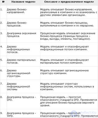
Table 7 describes the business models used to describe the organizational and functional activity, which corresponds to the sections “Business
processes and organizational structure.
Table 7. Models of Betec methodology (©) corresponding to the sections "Business Process" and "Organizational Structure".
The “Business Trees Tree” model is used to describe business directions implemented in a company and their relationship with other elements of the organization (Fig. 23).
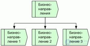
Fig. 23. Business Trees Model - Betec (©).
The Business Process Tree model describes the business processes performed in a company and their hierarchy (Fig. 24). At the top level of the tree, business processes are divided into three groups: basic, supporting and managerial.
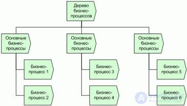
Fig. 24. Модель "Дерево бизнес-процессов" - Betec (©).
Модель "Диаграмм окружения процесса" позволяет описать окружение или границы бизнес-процесса, показывая его входы, выходы, поставщиков и клиентов (рис. 25).
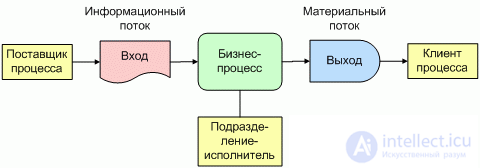
Рис.25. Модель "Диаграмма окружения процесса" - Betec (©).
Модель "Дерево информационных потоков" позволяет описать и классифицировать информационные потоки компании, которые представляют из себя информацию, размещенную на бумажных носителях, устную информацию либо информацию в электронном виде. Во многих проектах по описанию бизнес-процессов, также приходится описать внутреннюю структуру информационных потоков. Для решения этой задачи, удобным с практической точки зрения, является подход, когда структура информации описывается в виде документа MS Word, после чего на схеме дерева информационных потоков показывается соответствие между элементами дерева и разработанными документами (рис. 26).
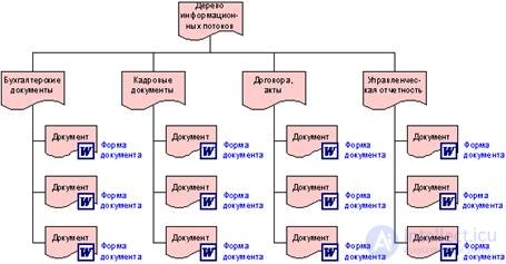
Fig. 26. Модель "Дерево информационных потоков" - Betec (©).
Модель "Дерево материальных потоков" позволяет описать и классифицировать материальные потоки компании, которые представляют из себя сырье, полуфабрикаты, готовую продукцию и т.д. (рис. 27).
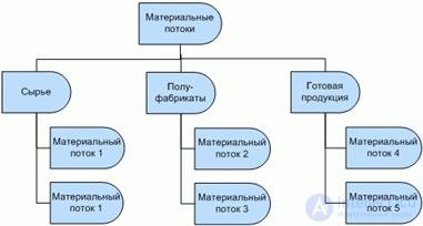
Fig. 27. Модель "Дерево материальных потоков" - Betec (©).
Модель "Дерево организационной структуры" используется для описания организационной структуры компании. На данной модели изображаются структурные подразделения, должности, а также связи линейного и функционального подчинения (рис. 28).
На практике приходится разрабатывать несколько различных типов моделей организационной структуры, основными из которых являются модели организационной структуры, построенные по принципу подчиненности и принципу входимости. Это связано с тем что в некоторых случаях на одной модели невозможно наглядно показать все имеющиеся взаимодействия между структурными подразделениями. В данном случае строят несколько простых моделей, на каждой из которых отображают только один тип взаимодействий.
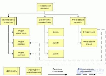
Fig. 28. Модель "Дерево организационной структуры" - Betec (©).
Модель "Дерево информационной систем" используется для описания структуры информационных систем, используемых в компании. На данной модели показываются типы информационных систем применяемых в компании, описывается их модульная структура, а также перечисляется программное обеспечение, используемое в компании при выполнении бизнес-процессов. (рис. 29).
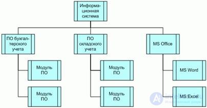
Fig. 29. Модель "Дерево информационной системы" – - Betec (©).
Модель "Диаграмма процесса - DFD" является прототипом классического DFD–стандарта и используется для описания бизнес-процессов верхнего уровня. При построении диаграммы процесса – DFD описываются работы из которых состоит бизнес-процесс, а также используются элементы организационной структуры, информационных систем, материальных и информационных потоков, которые были описаны при построении бизнес-моделей, рассмотренных выше.
В случае если в проекте была описана внутренняя структура информационных потоков, то на схеме процесса показывается соответствие между элементами информационных потоков и документами в формате MS Word, описывающих внутреннюю структуру информации (рис. 30).
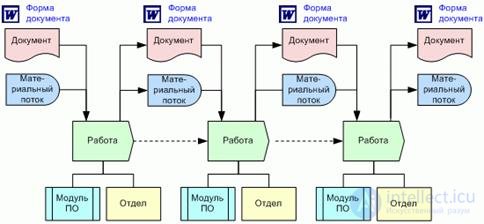
Fig. 30 Модель "Диаграмма процесса - DFD" – - Betec (©).
Модель "Диаграмма процесса - WFD" является прототипом классического WFD–стандарта и используется для описания бизнес-процессов нижнего уровня. При построении диаграммы процесса – WFD описываются работы, из которых состоит бизнес-процесс, а также используются элементы организационной структуры, информационных систем, материальных и информационных потоков, которые были описаны при построении бизнес-моделей, рассмотренных выше.
В случае если в проекте была описана внутренняя структура информационных потоков, то на схеме процесса показывается соответствие между элементами информационных потоков и документами в формате MS Word, описывающих внутреннюю структуру информации (рис. 31).
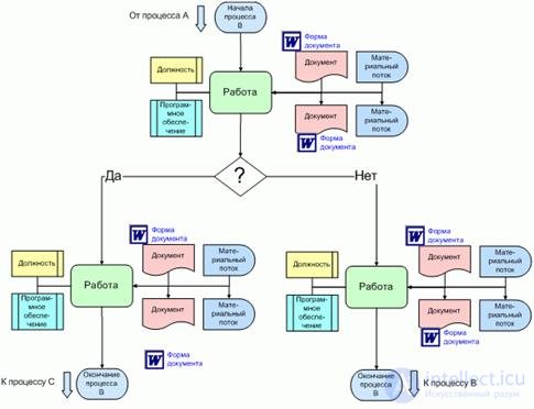
Fig. 31 Модель "Диаграмма процесса - WFD" – - Betec (©).
1.14 Методология BAAN
Методология описания деятельности, разработанная компанией разработчиком информационных систем BAAN содержит бизнес-моделей, описание которых приведено в таблице 8.
Таблица 8. Модели методологии BAAN.
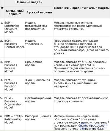
С помощью данных бизнес-моделей последовательно описываются функции, бизнес-процессы, организационная и информационная структура предприятия. Давайте рассмотрим структуру и основное предназначение данных бизнес-моделей.
Модель метаструктуры предприятия – ESM применяется для описания географически распределенной организационной структуры предприятия, описывает географические подразделения компании (офисы, филиалы, пр.), а также материальные и информационные потоки между ними. Данная бизнес-модель по своей сути напоминает классический DFD- стандарт, в котором на разрабатываемой схеме вместо работ, показываются структурные подразделения и взаимодействия между ними (рис. 32)
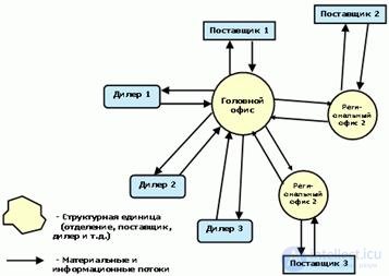
Fig. 32. Модель метаструктуры предприятия – ESM / BAAN.
Структурные подразделения компании, изображенные на модели метаструктуры предприятия – ESM декомпозируется на модель управления – BCM, на которой показываются бизнес-процессы данного структурного подразделения, а также материальные и информационные потоки протекающие между ними. Модель управления – BCМ полностью соответствуют классической DFD-схеме и она применяется для описания бизнес-процессов верхнего уровня (рис. 33).
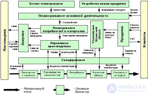
Fig. 33. Модель управления – BCM / BAAN.
Процессы с модели управления – BCM декомпозируются на модель управления – BCM более низкого уровня в случае, если они глобальны и могут быть представлены в виде временной последовательности работ. В противном случае они декомпозируются на модели бизнес-процессов – BPM, которые применяются для описания бизнес-процессов нижнего уровня и практически соответствуют классической WFD-схеме, за исключением двух особенностей. Первая – блоки принятия решений на модели бизнес-процессов BPM называются управляющими работами и вторая особенность связана с наличием на модели элементов, называемых состоянием, с помощью которых описываются состояния, характеризующие начало и окончания каждой работы. Данный подход, связанный с описанием состояний заимствован из подхода к описанию бизнес-процессов, который называется "Сети Петри" (рис. 34).
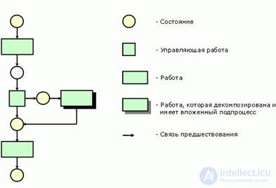
Fig. 34. Модель бизнес-процессов – BPM / BAAN.
При описании деятельности компании методология BAAN также использует модель функций – BFM, при помощи которых строится дерево функций компании (рис. 35).
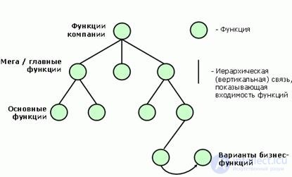
Fig. 35. Модель функций – BFM / BAAN.
Следующая модель методологии BAAN – модель организационной структуры – BOM используется для описания подразделений и должностей организации, а также связей линейного и функционального подчинения (рис. 36). На данной модели также показываются роли, которые играет должность в тех или иных бизнес-процессах. Например сотрудник, занимающий должность менеджер отдела маркетинга, может играть роль менеджера проекта в проекте по выводу нового проекта на рынок, при этом данный сотрудник может играть и другие роли в других проектах.
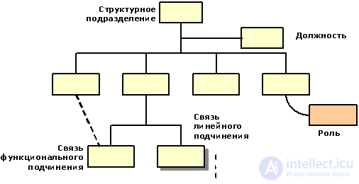
Fig. 36. Модель организационной структуры – BOM / BAAN.
Последняя информационная модель - ERM методологии BAAN имеет тип "Сущность-Связь" и предназначена для описания структуры информации, используемой при реализации бизнес-процессов. С помощью данной модели проектируется базы данных (рис. 37).

Fig. 37. Информационная модель – ERM / BAAN.
Аналитический раздел
Объект управления: Риэлторская компания (Корпорация «Инком-Недвижимость»). Основные направления деятельности компании – создание пригородных жилых комплексов малой и средней этажности, а также осуществление сделок с жилой и коммерческой недвижимостью в Московском регионе, Кирове и Красноярске. Одним из главных условий успешного бизнеса риэлторской компании, является хороший подбор персонала. Так как именно высококлассные специалисты обеспечивают высокую прибыль компании. Набор персонала, увольнение, смена должности, обучение персонала – эти процессы, являются такими же важными, как и процессы связанные с не посредственной деятельностью компании.
Риэлторские компании имеют максимально простую организационную структуру в форме головного офиса и дополнительных региональных офисов, что не несет организационные факторы риска и несущественно влияет на деятельность компаний. Для риэлторских компаний более значимым являются отраслевые факторы риска и операционные риски. В состав Инком-недвижимости входят 31 офис в Москве и региональные представительства в Красноярске, Алма-Ате, Кирове. Управление и структура агентства недвижимости(рис 38).
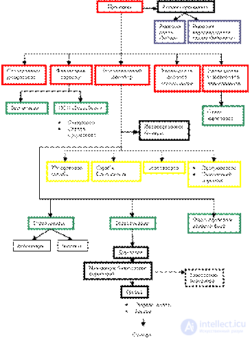
Fig. 38 Структура агентства недвижимости
Обеспечение служб, риэлторской компании:
Техническое: Рабочие места персонала обеспечены персональными компьютерами последних моделей, локальной сетью и выходом в интернет, также всей необходимой орг. Техникой и канцелярскими принадлежнастями.
Программное: Использование системы Microsoft Dynamics CRM 3.0 в качестве связующей среды для работы сотрудников, взаимодействующих с клиентами корпорации «ИНКОМ-Недвижимость»( единой базы данных поставщиков, клиентов корпорации), использование лицензионного ПО (т.к. антивирусы, брандмауэры, браузеры)
Обеспечение Кадрами: Набор и обучение высококлассных специалистов, так как от профессионализма сотрудников напрямую зависит прибыль компании.
3. Проектный раздел.
3.1 Постановка задачи.
На каждом предприятии существует такая проблема как текучесть кадров. Тем более такая проблема преследует крупные компании. Увольнения, найм на работу, это множество документов и работы с ними. Существует возможность ошибки, при работе с таким количеством документов. Утери трудовых книжек, или неправильное их оформление.. Для этого отдел кадров агенства должен проверить правильность оформления обходных листов, записей в трудовой книжке и в книге учета хранения..
Задача: Выдать увольняющемуся сотруднику трудовую книжку, с записью в книгу учета хранения и выдачи трудовых книжек и с обязательной проверкой записей в обходном листе.
3.2 Экономическая сущность задачи.
Цель – выдать увольняющемуся сотруднику трудовую книжку; вход – обходной лист, выход – заполненный обходной лист, трудовая книжка ; задача не периодична и выполняется по мере необходимости.
3.3 Описание метода решения задачи.
Задача решается по методологии DFD-схемы бизнес-процесса в нотации Гейна-Сарсона показанному ниже на рисунке 39.
3.4 Описание бизнес-процесса.
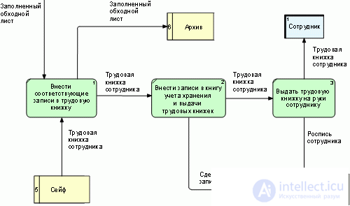
Fig. 39 DFD-схема бизнес-процесса "Оформлении и выдача трудовой книжки сотруднику при увольнении".
Дополнительные информация и схемы по данной функциональности, расположены в разделе ПРИЛОЖЕНИЯ, ДОПОЛНИТЕЛЬНЫЕ ЗАДАНИЯ.
Conclusion
Моделирование бизнес-процессов позволяет проанализировать не только, как работает предприятие в целом, как оно взаимодействует с внешними организациями, заказчиками и поставщиками, но и как организована деятельность на каждом отдельно взятом рабочем месте.
Моделирование бизнес-процессов организации включает два этапа структурное и детальное.
Под методологией (нотацией) создания модели (описания) бизнес-процесса понимается совокупность способов, при помощи которых объекты реального мира и связи между ними представляются в виде модели.
Основу многих современных методологий моделирования бизнес-процессов составила методология SADT (Structured Analysis and Design Technique – метод структурного анализа и проектирования) и алгоритмические языки, применяемые для разработки программного обеспечения. С помощью методологии семейства IDEF можно эффективно отображать и анализировать модели деятельности широкого спектра сложных систем в различных разрезах. Система ARIS представляет собой комплекс средств анализа и моделирования деятельности предприятия. Ее методическую основу составляет совокупность различных методов моделирования, отражающих разные взгляды на исследуемую систему.
Необходимо учитывать важные характеристики моделирования бизнес-процессов. В частности, к преимуществам моделирования бизнес-процессов относят: повышение качества и скорости производства продукции с одновременным снижением издержек; рост профессионализма сотрудников; повышение конкурентоспособности компании. Недостатки, в свою очередь: усиление эксплуатации сотрудников и связанные с этим проблемы социально-психологического характера; необходимость проведения целенаправленной работы по изменению корпоративной культуры.
Стандарт графического описания абстрактной модели системы. UML was created to define, visualize, design, and document mainly software systems.
The use of UML is not limited to software modeling. Его нередко используют для моделирования бизнес процессов, системного проектирования и отображения организационных структур.
Следующие типы диаграмм используются при моделировании бизнес процесса:
Comments
To leave a comment
Analysis and reengineering of business processes
Terms: Analysis and reengineering of business processes